

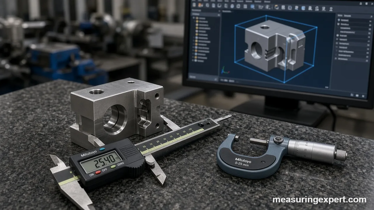
3D modeling helps engineers measure by turning a part into exact digital geometry. From the model, software reports lengths, angles, areas, volumes and mass before anything is built. For example, a CAD model of a 100 x 50 x 20 mm block instantly gives 100 cm3. However, a real part still varies within its tolerance, so it needs checking.
Convert Millimeters, Inches and Mils for 3D Modeling
Unit mix-ups are a classic 3D modeling mistake, so check your units first. Enter a size below and pick millimeters, inches or mils (thousandths of an inch). The converter uses the exact definition 1 inch = 25.4 mm.
Engineers use 3D modeling to design parts, test how they fit and read their dimensions without touching metal. As a result, many measurement questions are now answered on a screen first. However, a model is a plan, not the finished part, so this guide shows what the model can tell you and where you still need a gauge.
Below, you will find a tolerance chart, a comparison of model types, a worked example with real arithmetic, and a step list for checking a part against its model. In addition, the FAQ covers the questions people ask most about 3D modeling in engineering.
3D Modeling Tolerance and Unit Chart
Engineering drawings quote tolerances in millimeters, inches or mils, depending on the shop. This chart converts the sizes that come up most. Each value follows from 1 in = 25.4 mm exactly.
| Inches | Mils | Millimeters |
|---|---|---|
| 0.0005 in | 0.5 mil | 0.0127 mm |
| 0.001 in | 1 mil | 0.0254 mm |
| 0.002 in | 2 mil | 0.0508 mm |
| 0.005 in | 5 mil | 0.127 mm |
| 0.010 in | 10 mil | 0.254 mm |
| 1/64 in | 15.625 mil | 0.397 mm |
| 1/16 in | 62.5 mil | 1.5875 mm |
| 1 in | 1,000 mil | 25.4 mm |
Many shops quote tolerances as plus or minus values. For example, a tolerance of +/-0.05 mm is about +/-0.002 in. For more exact factors, see our guide to imperial to metric conversions.
Recommended Tools to Check 3D Modeling Dimensions
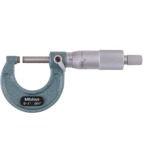
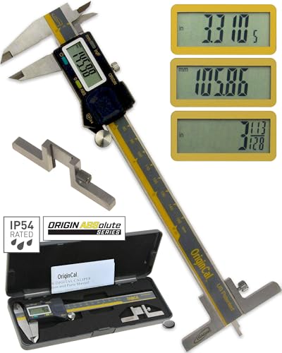
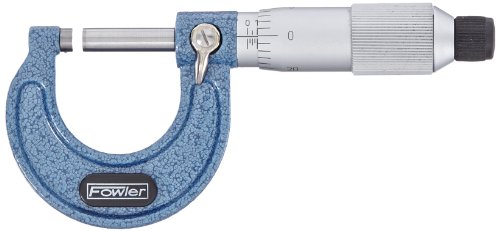
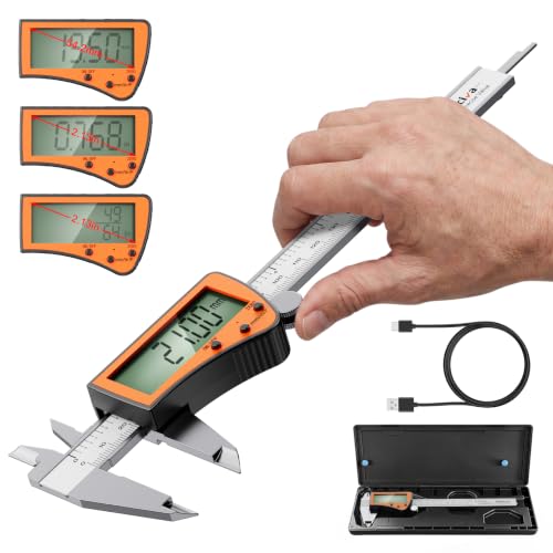
A model tells you what a part should measure, and a gauge tells you what it does measure. First, a digital caliper covers most outside, inside and depth checks. Next, a micrometer reads smaller sizes more finely when a tight tolerance applies. Also, pick tools that switch between inches and millimeters, because models and drawings often use both.

As an Amazon Associate, Measuring Expert earns from qualifying purchases.
Key Takeaways
- 3D modeling gives exact nominal dimensions, volumes and mass before a part exists.
- A real part always varies, so tolerances and gauges still matter.
- 1 in = 25.4 mm exactly, and 1 mil = 0.0254 mm.
- Solid CAD models are exact; meshes and point clouds are approximations.
- A wrong import unit can scale a part by 25.4 times.
- Tolerance stacks grow as parts are added, so check the total, not each part.
- Use a calibrated lab for parts with tight or safety-critical tolerances.
What 3D Modeling Means in Engineering Measurement
3D modeling is the process of building a digital object in three dimensions. In engineering, the object is usually a computer-aided design (CAD) model with exact geometry. Therefore, the software can compute its size, surface area, volume, center of mass and the distance between any two features.
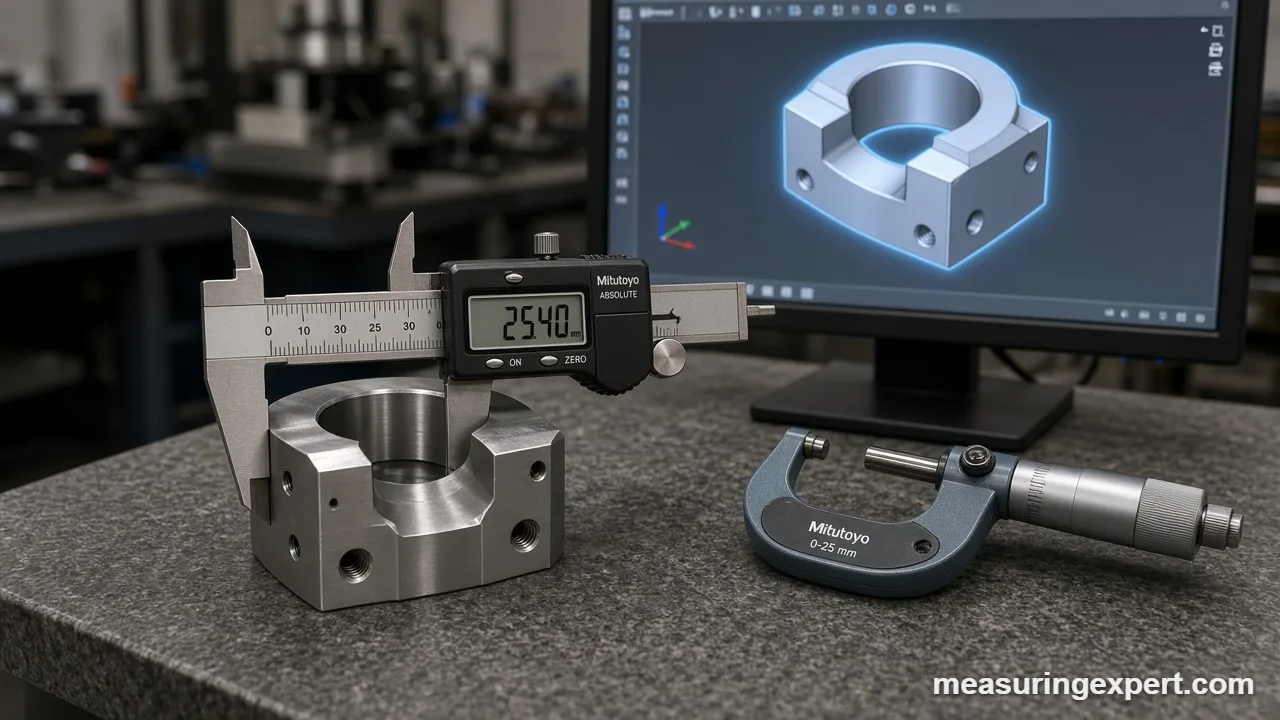
Models also carry the measurement rules for the part. The NIST report On Migrating ISO 10303 PMI Models to a Common Core describes the move from drawing-based exchange to model-based exchange of product and manufacturing information. In short, tolerances and notes can now travel inside the 3D file, and ISO 10303-242 (AP 242), published in 2014, is the STEP standard that supports it.
Because STEP is a neutral format, a design team and a machine shop can open the same model in different software. As a result, both sides read the same dimensions.
How a Model Gives You Dimensions
Also, most CAD programs include a measure tool. First, you pick two points, edges or faces. Then the software reports the distance, angle or radius between them. Finally, a mass-properties tool combines volume with the density you assign to give weight.
In fact, the numbers come from the geometry, not from pixels on the screen. Consequently, zooming in does not change a result. A distance between two holes is exact to the model’s stored precision, as long as the units are right.
You can also pull dimensions into a drawing. In that case, the drawing updates when the model changes, which avoids retyping and the errors that come with it.
Nominal Size vs Real Parts: Why Tolerances Matter
First, a model holds the nominal size, which is the ideal. A shop cannot make every part exactly ideal, so a drawing adds a tolerance, which is the allowed range. For example, a shaft with a nominal diameter of 25.4 mm and a tolerance of +/-0.05 mm is acceptable between 25.35 and 25.45 mm.
Tolerances also stack. Suppose four parts in a row each have a tolerance of +/-0.1 mm. In the worst case, the total length can be off by 4 x 0.1 = 0.4 mm. A statistical estimate, the root sum of squares, gives the square root of 4 x 0.1 x 0.1, which is 0.2 mm. Designers use both views, so the model alone never tells the whole story.
Solid, Mesh and Point Cloud Models Compared
However, not every 3D file is equally exact. The table shows what each type is good for.
| Model type | What it is | Best use | Measurement caution |
|---|---|---|---|
| Solid CAD (such as STEP) | Exact curves, planes and holes | Design and tolerance work | Shows nominal size only |
| Mesh (such as STL) | Many small triangles | 3D printing and visuals | Curves are approximated by flat facets |
| Point cloud | Millions of scanned points | Comparing a real part with its model | Accuracy depends on the scanner and setup |
For instance, a mesh replaces a smooth curve with straight facets. Fewer, larger triangles mean a larger gap between the true curve and the facets. Therefore, a rough mesh can read a cylinder slightly small. Our guide to laser scanning vs traditional measurement explains how scans of real parts are compared with models.
Worked Example: Mass and Tolerance From a Model
Here is a small example with the arithmetic shown. Suppose a CAD model shows an aluminum block that is 100 mm long, 50 mm wide and 20 mm thick.
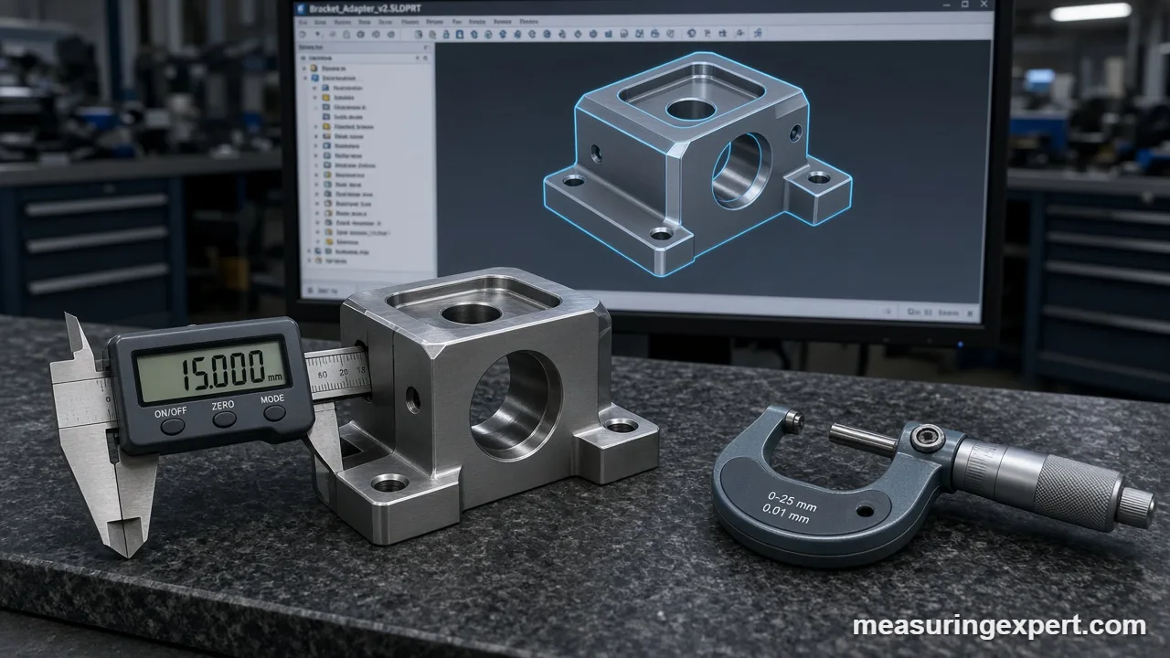
First, the volume is 100 x 50 x 20 = 100,000 cubic millimeters. Since 1 cubic centimeter is 1,000 cubic millimeters, that is 100 cm3. Next, aluminum has a density of about 2.7 g/cm3, so the mass is 100 x 2.7 = 270 g. In pounds, that is 270 / 453.59237 = about 0.595 lb.
Then check the size in inches. The block is 100 / 25.4 = 3.937 in long, 1.969 in wide and 0.787 in thick. If the drawing allows +/-0.1 mm on the thickness, the real part may be between 19.9 and 20.1 mm, which is 0.783 to 0.791 in.
How to Verify a 3D Modeling Dimension Step by Step
- Confirm the model units. Check the document settings for millimeters, inches or another unit before reading any value.
- Read the nominal and tolerance. Find the target size and its allowed range on the drawing or in the model notes.
- Measure the feature in the model. Use the measure tool between the exact points you plan to gauge.
- Choose a suitable gauge. Pick a caliper or micrometer that reads finer than the tolerance.
- Measure the real part. Take several readings at different spots, because parts are rarely perfectly uniform.
- Compare and record. Check that the readings fall inside the tolerance, and note any part that does not.
Do and Don’t When Using Model Dimensions
Do
- Confirm the unit system on import.
- Use a gauge that resolves finer than the tolerance.
- Calibrate your tools on a schedule.
- Keep the tolerance next to the nominal size.
- Check the total of stacked tolerances.
Don’t
- Read an STL mesh as if it were exact geometry.
- Assume a printed part matches the model.
- Round a tolerance before converting units.
- Trust one reading on a single spot.
- Skip the material density when you estimate weight.
For tool checks, read about why measurement tools need calibration.
Honest Limits of 3D Modeling
3D modeling is powerful, yet it has limits. For one thing, a model describes the design, not the manufactured part. For example, machines wear, materials shrink, and temperature changes a part’s size slightly. Moreover, a model with a wrong unit or a missing feature can produce a confident but wrong number.
Scale errors are the most common trap. For instance, a model built in inches but imported as millimeters comes out 25.4 times too small. In short, always sanity-check one known dimension after an import.
Finally, model accuracy is not the same as measurement accuracy. In fact, the model may be exact while your gauge, scanner or technique adds error. Our article on measurement precision explains how small errors add up.
When to Call a Professional
Hire an accredited calibration or inspection lab when a tolerance is tight, a part is safety-critical, or a customer requires a formal report. Labs use coordinate measuring machines (CMMs), and the ISO 10360 series defines how those machines are tested. Part 1 sets the terms used in acceptance and reverification testing of CMMs. Likewise, ask a licensed engineer to review any design that carries structural loads.
Frequently Asked Questions
Why is 3D modeling important in engineering?
3D modeling lets engineers check size, fit and mass before building anything. It cuts errors, speeds up design changes and gives every team the same dimensions.
What is 3D modeling in mechanical engineering?
It is the use of CAD software to build digital parts and assemblies with exact geometry. Engineers then measure features, test how parts fit and prepare drawings from the model.
What is the purpose of 3D modeling?
The purpose is to describe an object in three dimensions so it can be designed, measured, simulated and made. In engineering, it also stores the tolerances that decide whether a part passes.
How accurate are dimensions from a 3D model?
A solid CAD model is exact to its stored precision for the nominal size. A real part still differs by its manufacturing error, so you check it with a gauge.
What is the difference between nominal size and tolerance?
The nominal size is the target dimension in the model. The tolerance is the allowed variation, such as +/-0.05 mm, around that target.
How many inches is 25.4 mm?
25.4 mm is exactly 1 inch. This is the international definition used in CAD software and on drawings.
Can I measure a real part against its 3D model?
Yes. You can gauge key features by hand or scan the whole part and compare the point cloud with the model. Scanning shows deviations as a map across the surface.
Why does my 3D print not match the model size?
Printing adds its own error from shrinkage, layer height and machine settings. Measure the printed part with calipers and adjust the model or the settings.
What does STEP mean in 3D modeling?
STEP is the neutral file format defined by ISO 10303. It lets different CAD programs exchange exact geometry and, in newer versions, tolerances.
How do I calculate the weight of a part from its model?
Multiply the model’s volume by the material density. For 100 cm3 of aluminum at about 2.7 g/cm3, the mass is about 270 g.
The Bottom Line on 3D Modeling and Measurement
To sum up, 3D modeling gives engineers exact nominal dimensions, volumes and mass before a part is made. Real parts, however, vary within their tolerances, so a model never replaces a gauge. The strongest workflow uses both.
So confirm your units, read the tolerance and measure the real part with a suitable tool. Use the converter at the top whenever a drawing and a model disagree on units, and hand tight or critical checks to an accredited lab.