

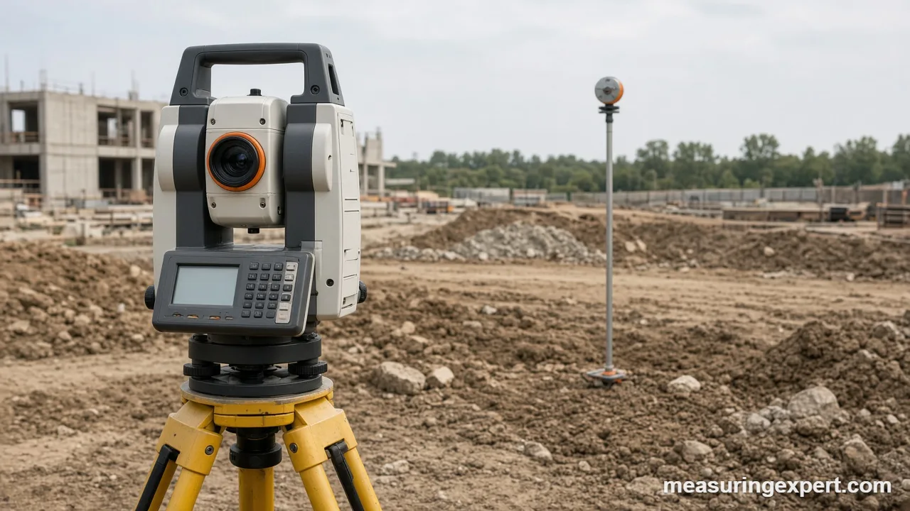
A total station is a survey instrument that measures horizontal angles, vertical angles and slope distance from one tripod setup. To use a total station, level it over a known point, aim at a backsight, then shoot a prism at each point you need. The built-in computer returns coordinates.
Total Station Distance Converter: Meters, Feet and Inches
Most models record distance in meters or feet. To start, use the converter below to check a reading in the other unit. It uses the exact international foot of 0.3048 m, so the results match what a current data collector shows.
This instrument looks complicated, yet the job is simple. In short, it measures two angles and one distance, then does the trigonometry for you. As a result, one person can lay out a building corner, check a slab or record a ditch in minutes. This guide shows how a total station works, how to set one up, and which specs actually matter.
First, you will see how the instrument measures. Next comes a step-by-step setup. After that, the guide covers accuracy, layout work, common mistakes, care and the point where you should call a licensed surveyor.
- How a total station works
- Recommended tools for total station work
- How to set up a total station
- Total station accuracy explained
- Total station vs theodolite vs laser measure
- Collecting and staking out points
- Total station units and the survey foot
- Mistakes, do and don’t
- Care and field checks
- Honest limits
- When to call a licensed surveyor
- FAQs
How a Total Station Works
A total station combines three parts in one housing. First, an electronic theodolite reads angles. Second, an electronic distance meter (EDM) sends a beam to a target and times its return. Finally, a small computer stores the readings and turns them into coordinates.
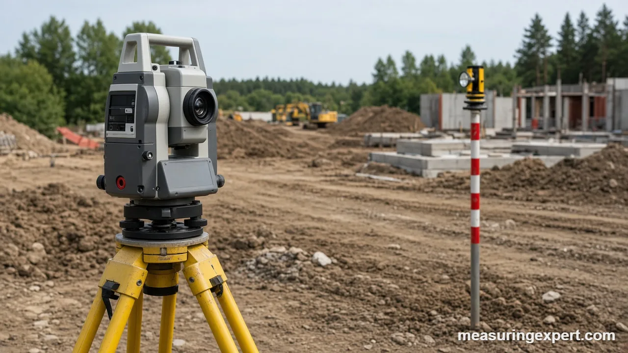
In practice, every shot gives three raw numbers: a horizontal angle, a vertical angle and a slope distance. The vertical angle is usually a zenith angle, which counts down from straight up. Therefore, a level line of sight reads 90 degrees, and a shot aimed up reads less.
From those numbers the instrument works out the horizontal distance and the height difference. For example, take a slope distance of 50.000 m at a zenith angle of 85 degrees. The horizontal distance is 49.810 m, and the rise is 4.358 m.
Horizontal distance = slope distance x sin(zenith angle)
Height difference = slope distance x cos(zenith angle) + instrument height – target height
With an instrument height of 1.550 m and a target height of 1.500 m, the point sits 4.408 m above the station. In addition, the horizontal angle from a known backsight gives the direction. Together, distance and direction produce northing, easting and elevation for the point.
Overall, prism targets give the longest range and best accuracy. Many models also measure without a prism by reflecting off a wall or a pile. This reflectorless mode is handy for hard-to-reach spots, for example a high wall. However, its range is shorter and the beam can scatter on dark or wet surfaces.
Recommended Tools for Total Station Work
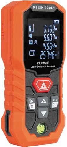
The instrument is only part of the kit. First, a solid tripod keeps the station from drifting during a long session. Next, a prism pole with a bubble holds the target plumb. Also, a plumb bob or laser measure gives a quick backup check. Also, pick gear that fits your instrument’s thread, which is normally 5/8-11 for the tribrach and tripod head.



As an Amazon Associate, Measuring Expert earns from qualifying purchases.
Key Takeaways
- A total station measures horizontal angle, vertical angle and slope distance, then computes coordinates.
- Setup always follows the same order: tripod, level, plumb, enter the station, sight the backsight.
- Measure the instrument height and target height every time, because a wrong height shifts every elevation.
- Published accuracy is two numbers: an angle figure in arcseconds and a distance figure such as 2 mm + 2 ppm.
- Angle error grows with range, and the ppm part of the distance error grows with range too.
- Check the setup with a known point before you stake anything.
- Legal boundaries and structural layout belong to a licensed surveyor.
How to Set Up a Total Station Step by Step
Follow this order on every job. Skipping a step usually costs more time later than it saves now, so keep the order.
- Plant the tripod. Spread the legs so the head sits roughly level and about chest height, directly over the control point.
- Mount the instrument. Place the instrument on the tripod head and tighten the central screw. Then switch on the laser plummet.
- Center over the point. Move the tripod legs until the laser dot sits on the mark. After that, press the legs firmly into the ground.
- Level the instrument. Adjust the tripod leg lengths to center the round bubble. Next, use the foot screws to center the electronic bubble.
- Recheck the plummet. Slide the instrument slightly on the head if the dot drifted. Then level again.
- Enter the station data. Type the station name, its coordinates and the instrument height. Also set the temperature and pressure for the distance correction.
- Sight the backsight. Aim at a second known point and set the direction. Finally, shoot a third known point as a check.
For example, surveyors use a free station setup when no convenient control point exists. In that case, the instrument shoots two or more known points and computes its own position. This method is common on busy sites, because you can place the tripod where the work is.
Total Station Accuracy: What the Specs Mean
In general, every total station lists two accuracy figures. The first covers angles, measured in arcseconds. For reference, one arcsecond is 1/3,600 of a degree. The second covers distance and has a fixed part plus a part per million (ppm) of the distance.
As an example, one published listing gives 2 arcseconds for angles and 2 mm + 2 ppm for prism distances, with a prism range of 5,000 m (GeoMatching specification listing). Other models differ, so always read the sheet for your own instrument.
| Spec | At 100 m | At 500 m | At 1,000 m |
|---|---|---|---|
| Angle error, 1 arcsecond | 0.48 mm sideways | 2.42 mm | 4.85 mm |
| Angle error, 2 arcseconds | 0.97 mm | 4.85 mm | 9.70 mm |
| Angle error, 5 arcseconds | 2.42 mm | 12.12 mm | 24.24 mm |
| Distance error, 2 mm + 2 ppm | 2.2 mm | 3.0 mm | 4.0 mm |
In short, a 2-arcsecond instrument at 100 m places a point within about 1 mm sideways and about 2 mm along the line. Remember that this figure is the instrument’s own limit. In practice, centering, leveling, the prism pole and the weather add error on top.
Total Station vs Theodolite vs Laser Measure
People often mix up these three tools. Each one suits a different job, so the table below separates them clearly.
| Tool | Measures | Typical use | Gives coordinates? |
|---|---|---|---|
| Total station | Horizontal angle, vertical angle, distance | Layout, topographic surveys, as-built checks | Yes |
| Theodolite | Horizontal and vertical angles only | Angle work, alignment, teaching | No, unless paired with a tape or EDM |
| Handheld laser measure | Distance only | Room dimensions, quick checks | No |
If you only need angles, read our guide on how to use a theodolite. For smaller rooms and quick distances, a laser measure is faster and far cheaper. For a broader look at angle tools, see tools for measuring angles.
Collecting and Staking Out Points on a Construction Site
The instrument does two main jobs. In collection mode, it records the position of existing features. In stakeout mode, however, it guides you to a position from the plans.
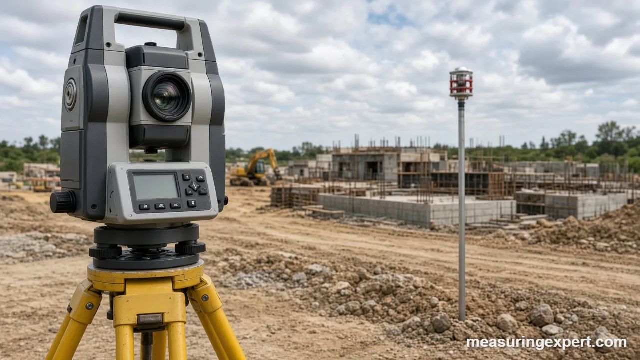
First, for collection, hold the prism pole plumb on the feature and trigger a shot. Then enter a code that names the feature, such as a curb, a corner or a pipe invert. As a result, consistent codes save hours when the data goes into CAD.
For stakeout, load the design points into the data collector. Next, the screen tells you how far to move the prism left, right, forward or back. Finally, when the offsets read zero, mark the spot with a stake or paint.
Slope also matters on site, for instance when you check a ramp. If your vertical angle reads 5 degrees above level, the line rises about 8.75 m per 100 m of horizontal distance. For quick checks indoors, a laser level is often enough.
Total Station Units, Meters and the US Survey Foot
Most models can display meters, international feet or US survey feet. However, the two feet differ slightly. The international foot is exactly 0.3048 m. The US survey foot is about 0.3048006 m, which is roughly 2 parts per million longer.
At first, that gap looks tiny. However, it adds up across large coordinates. Over one mile, it comes to about 0.01 ft, and in state plane coordinates it can shift positions by a few feet. For this reason, the US federal government deprecated the survey foot after December 31, 2022. Newer data should use the international foot (Federal Register notice).
| Unit | Exact or approximate | Meters |
|---|---|---|
| International foot | Exact | 0.3048 m |
| US survey foot (legacy) | 12/39.37 m, approximate | 0.3048006 m |
| Inch | Exact | 0.0254 m |
Therefore, before you start a job, confirm which foot the project coordinates use. Likewise, set the unit option on the instrument to match the data collector and the plans.
Common Total Station Mistakes
Do
- Level and plumb the instrument before every session.
- Measure instrument and target heights with a tape.
- Check a known point before and after the work.
- Set the temperature and pressure correction.
- Keep the prism pole bubble centered on every shot.
Don’t
- Leave the instrument alone on an unstable tripod.
- Mix feet and meters between the instrument and the plans.
- Aim the telescope at the sun.
- Trust one backsight with no check shot.
- Shoot long distances through heat shimmer.
Care and Field Checks for Your Total Station
Overall, a well-kept instrument holds its accuracy for years. First, carry it in its case and tighten the clamps only lightly during transport. Next, wipe lenses with a lens brush or clean cloth, not a shirt sleeve.
In addition, run a simple field check each season. Set up the instrument, shoot a point in face left, flip the telescope and shoot it again in face right. Then the two horizontal readings should differ by exactly 180 degrees. If they do not, the collimation needs adjusting, so send the unit to a service center.
Meanwhile, heavy impacts, large temperature swings and long storage can shift the settings. Therefore, many companies schedule professional calibration at least once a year, and after any drop.
Honest Limits of a Total Station
This instrument is precise, but it is not magic. For example, the beam bends slightly through warm and cold air layers. Over long distances, earth curvature and refraction also affect heights, so the software adds a correction that is only an average.
Moreover, the result is only as good as the control points. For instance, if the backsight coordinates are wrong by 20 mm, every point you stake carries that error. For these reasons, accuracy numbers on a spec sheet describe the best case, not every job.
When to Call a Licensed Surveyor
A homeowner or contractor can use one for internal layout, quantity checks and as-built records. However, some work legally needs a licensed professional.
- Property boundaries. For instance, only a licensed land surveyor can establish or certify a legal line.
- Structural layout. Foundations and anchor bolts for large buildings need verified control.
- Permits and plats. Also, many jurisdictions require stamped drawings.
- Disputes. A signed survey carries weight that a DIY measurement does not.
Frequently Asked Questions
What is a total station used for?
It measures angles and distances to record or mark positions. Crews use it for construction layout, topographic surveys, road work and as-built checks.
How do you use a total station in construction?
Set it up over a known point, level it and sight a backsight. Then shoot design points in stakeout mode and mark each spot once the offsets read zero.
How does the instrument measure distance?
It sends a modulated beam to a prism or surface and measures how the returning signal shifts. The unit converts that shift into a slope distance.
How accurate is a total station?
Accuracy varies by model. One published example lists 2 arcseconds for angles and 2 mm + 2 ppm for prism distances, so read your own spec sheet.
Total station vs theodolite: what is the difference?
A theodolite reads angles only. A total station adds a distance meter and a computer, so it can output coordinates.
How do you measure coordinates with a total station?
Enter the station coordinates and a backsight direction, then shoot the target. The instrument adds the measured offsets to the station values and shows northing, easting and elevation.
What is the prism for?
The prism is a reflector that sends the beam straight back to the instrument. It gives longer range and better accuracy than reflectorless mode.
Can one person run it alone?
Yes, with a robotic model. A robotic model follows the prism automatically, so one person can hold the pole and control the instrument.
How often should it be calibrated?
Many companies check it yearly and after any drop or impact. Follow your manufacturer’s schedule and quick field checks in between.
Is the US survey foot still used?
It was deprecated after December 31, 2022. New work should use the international foot of exactly 0.3048 m, though old data may still use the survey foot.
Total Station Bottom Line
To sum up, a total station turns two angles and a distance into coordinates. If you level it carefully, measure heights with a tape and check a known point, it lays out work with millimeter-level repeatability.
Finally, keep the limits in mind. Boundaries and structural layout need a licensed surveyor, and every spec sheet describes ideal conditions. Use the converter at the top for quick meter and foot checks, then match your project’s units before you stake.