

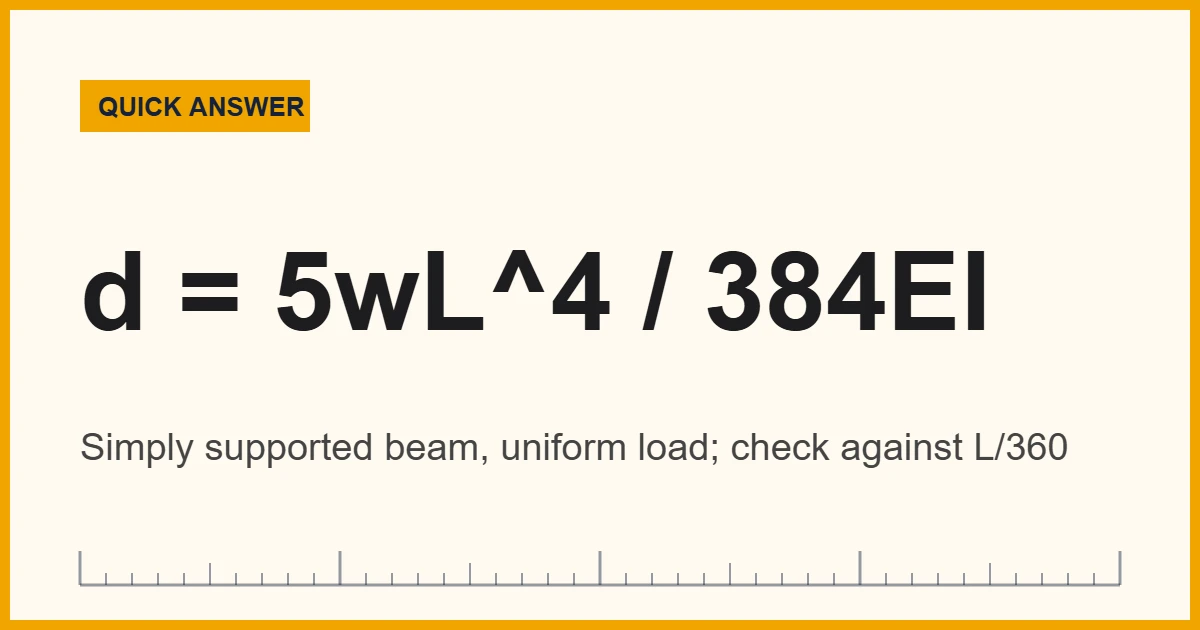
Beam deflection is how far a beam sags under load. To calculate it, use the formula for your support and load case, such as 5wL^4 / (384EI) for a simply supported beam with a uniform load. To measure it, compare a midspan reading with readings taken over the two supports.
Every beam bends a little when you load it, because no material is perfectly rigid. For instance, a floor joist dips as you walk across a room, a shelf bows under books, and a steel girder settles slightly when a truck rolls over a bridge. Indeed, that movement is normal. Therefore, the real question is how much, and whether the amount stays inside the limits that keep floors from feeling bouncy and drywall from cracking.
In short: beam deflection depends on four things. In other words, these are the load, the span, the stiffness of the material (its modulus of elasticity, E) and the shape of the cross section (its moment of inertia, I). Span has by far the biggest effect, because it appears to the third or fourth power in every standard formula.
The formulas on this page are the classic elastic beam equations. For example, the American Wood Council publishes them with load diagrams in its free Design Aid No. 6, Beam Design Formulas with Shear and Moment Diagrams, a reference that designers of wood, steel and aluminum beams all use.
Below, you will also find a unit converter for your readings, the formulas for six common cases, two worked examples (one US, one metric), a step-by-step field method for measuring a real beam, and the code limits that tell you whether a result is acceptable.
Convert Beam Deflection Readings Between Inches and Millimeters
Dial indicators and calculations often mix units. So type a deflection or a span below and the converter shows it in millimeters, centimeters, inches and mils (thousandths of an inch). For instance, 0.467 in is the L/360 limit for a 14 ft span, which you will meet again in the examples.
The converter uses the exact definition 1 in = 25.4 mm. However, it handles units only; for the deflection itself, use the formulas and examples further down.
Recommended Tools for Measuring Beam Deflection
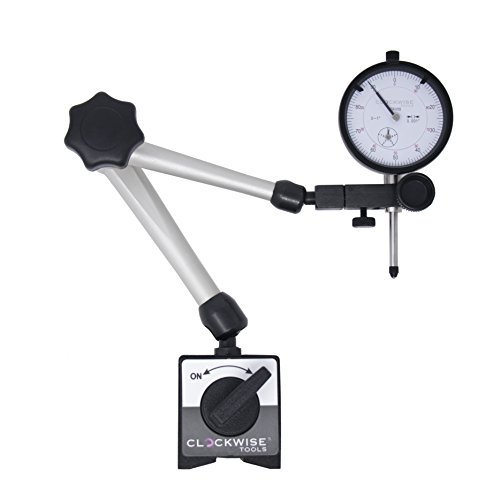
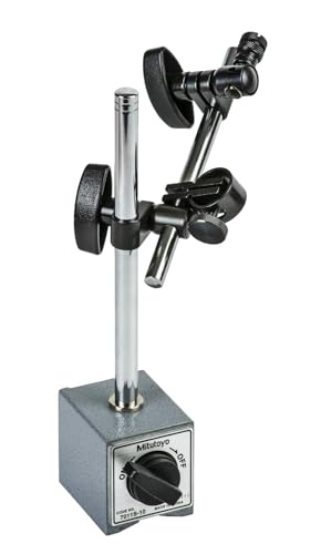
You do not need a lab to measure sag. First, a dial indicator on a magnetic or clamp base reads small movements to 0.001 in (about 0.025 mm). Next, a self-leveling laser or a taut string line gives a stable reference across longer spans. Finally, a tape measure and digital calipers capture the span and the beam’s actual cross section, which you need for the calculation.
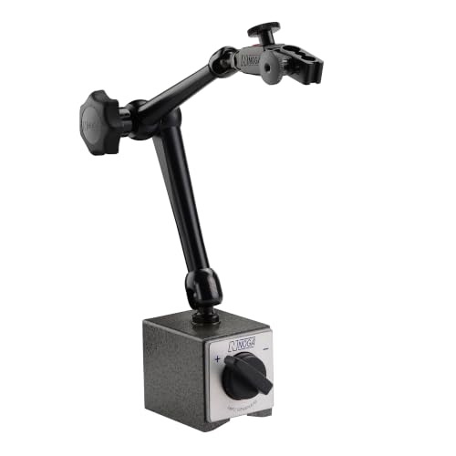



As an Amazon Associate, Measuring Expert earns from qualifying purchases.
Key Takeaways
- Beam deflection is the vertical movement of a beam under load, usually reported at midspan or at the free end.
- Each support and load case has its own formula; as a result, using the wrong one can be off by a factor of five or more.
- Deflection grows with the cube (point load) or fourth power (uniform load) of the span.
- Doubling a rectangular beam’s depth makes it eight times stiffer; however, doubling its width only doubles stiffness.
- Also, keep units consistent: pounds and inches, or newtons and meters, never a mix.
- US codes commonly limit floor live-load sag to span/360 and total sag to span/240.
- Measured sag should be the midspan reading minus the average of the two support readings.
What Beam Deflection Really Means
To begin with, a beam carries load by bending. The top fibers squeeze together and the bottom fibers stretch. As a result, the beam curves downward. Beam deflection is the size of that curve, measured as a distance: inches or millimeters at the point where the beam moves the most.
Moreover, where that point sits depends on the supports. On a beam resting on two supports, the largest sag is at or near the middle. By contrast, on a cantilever, such as a balcony or a diving board, it is at the free tip. Meanwhile, a beam fixed rigidly at both ends sags far less than the same beam simply resting on its supports, because the fixed ends resist rotation.
Deflection is a stiffness check, not a strength check. In fact, a beam can be strong enough not to break and still sag enough to crack a ceiling, make a floor feel springy, or keep a door from closing. For this reason, designers check both bending stress and deflection. For the stress side, see our guide on how to measure stress and strain in materials.
Beam Deflection Formulas for Common Cases
First, the table below lists the maximum deflection for the six cases people meet most often. In each one, P is a single point load, w is a uniform load per unit length, L is the span, E is the modulus of elasticity and I is the moment of inertia about the bending axis. All of them also assume a straight, prismatic beam made of a linear elastic material.
| Supports | Load | Maximum deflection | Where |
|---|---|---|---|
| Simply supported | Uniform load w | 5wL^4 / (384EI) | Midspan |
| Simply supported | Point load P at center | PL^3 / (48EI) | Midspan |
| Cantilever | Uniform load w | wL^4 / (8EI) | Free end |
| Cantilever | Point load P at free end | PL^3 / (3EI) | Free end |
| Fixed at both ends | Uniform load w | wL^4 / (384EI) | Midspan |
| Fixed at both ends | Point load P at center | PL^3 / (192EI) | Midspan |
Next, look at the constants. For example, a simply supported beam under a uniform load sags five times as much as the same beam with both ends fixed. Similarly, a cantilever with a point load at its tip sags 16 times as much as a simply supported beam of the same length with that load at midspan. Therefore, picking the right row matters more than any other step.
What Controls Stiffness: E, I and Span
The product EI is called flexural rigidity. Because a bigger EI means less sag, it helps to know where each part comes from.
| Term | What it describes | Typical values |
|---|---|---|
| E (modulus of elasticity) | How stiff the material is | Structural steel about 29,000 ksi (200 GPa); aluminum about 10,000 ksi (69 GPa); Douglas fir-larch No. 2 about 1,600 ksi (11 GPa) |
| I (moment of inertia) | How the cross section’s material is spread away from the bending axis | Rectangle: b x d^3 / 12; steel shapes: from the manufacturer or AISC tables |
| L (span) | Distance between supports, or the overhang length for a cantilever | Appears as L^3 or L^4 |
The old idea that “more cross-sectional area means less bending” is only half right. Instead, what counts is I, not area. For example, a 2×10 joist laid flat has the same area as one standing on edge, yet on edge it is about 38 times stiffer, because the depth is cubed. As a result, a tall, thin beam beats a short, wide one of the same weight.
Likewise, span works the same way in reverse. Under a uniform load, doubling the span multiplies the sag by 16. So, adding a post at midspan usually cuts deflection more than any upgrade in material.
Worked Examples in US and Metric Units
Example 1 (US): a wood floor joist. A Douglas fir-larch No. 2 2×10 joist spans 14 ft at 16 in on center and carries a 40 psf live load. First, find the load per joist: 40 psf x 16/12 ft = 53.33 lb/ft, or 4.444 lb/in. Next, find I from the actual size, 1.5 in x 9.25 in: 1.5 x 9.25^3 / 12 = 98.93 in^4. Then convert the span to inches: 14 x 12 = 168 in.
Now plug into the simply supported formula with E = 1,600,000 psi: 5 x 4.444 x 168^4 / (384 x 1,600,000 x 98.93) = 0.291 in (about 7.40 mm). The L/360 live-load limit for this span is 168 / 360 = 0.467 in, so the joist passes for live load.
Example 2 (metric): a steel beam. A simply supported steel beam spans 10 m and carries a uniform load of 5,000 N/m. Steel has E = 200 GPa, and the section has I = 0.0003 m^4. Therefore the sag is 5 x 5,000 x 10^4 / (384 x 200 x 10^9 x 0.0003) = 0.01085 m, or about 10.85 mm (0.43 in).
The L/360 limit is 10,000 mm / 360 = 27.8 mm, so this beam passes with room to spare. However, if the same beam were fully fixed at both ends, the sag would drop to about 2.17 mm.
Finally, check units at every step. For example, mixing feet and inches is the most common reason a hand calculation comes out 144 or 1,728 times too large or too small.
How to Measure Beam Deflection on a Real Beam
Calculation predicts sag; measurement, however, confirms it. This simple field method also works for joists, shelves, test beams and garage headers.
- Set a stable reference. Stretch a taut string line between the two supports, or set up a self-leveling laser line along the beam.
- Mark three points. Mark the beam at both supports and at midspan (for a cantilever, at the support and the free tip).
- Take unloaded readings. Measure from the reference to the beam at all three marks, or zero a dial indicator under midspan.
- Apply the load. Add a known load, such as sandbags or weights, and note the total weight and where it sits.
- Wait, then read again. Let the beam settle for a minute and repeat the readings at the same three marks.
- Correct for support movement. Subtract the average change at the two supports from the change at midspan; the result is the true beam deflection.
- Compare with the prediction. Calculate the expected sag for that load and check the measured value against it and against the code limit.
Measuring Methods Compared
Above all, the right instrument depends on how small the movement is and how far you can reach.
| Method | Typical resolution | Best for | Watch out for |
|---|---|---|---|
| Tape or rule from a string line | About 1/32 in (0.8 mm) | Visible sag in joists and shelves | String sag on long spans; parallax |
| Laser line and target scale | About 1/16 in (1.6 mm) at room distances | Long beams, ceilings, floors | Laser accuracy spec; vibration |
| Dial or digital indicator | 0.001 in or 0.01 mm | Lab test beams, machine frames | Needs a rigid, independent mount |
| LVDT or laser displacement sensor | Microns | Load tests and monitoring | Cost; needs a data logger |
For distances along the beam, a laser distance measurer speeds up span measurements. In addition, digital calipers capture the actual depth and width of lumber, which often differ from the nominal size.
Allowable Beam Deflection Limits
Of course, a calculated or measured number means little until you compare it with a limit. In the US, the International Building Code sets common limits in Table 1604.3, which state codes such as the Florida Building Code Table 1604.3 reproduce.
| Member | Live load (L) | Dead + live (D + L) | 14 ft span, L limit |
|---|---|---|---|
| Floor members | L/360 | L/240 | 0.467 in (11.9 mm) |
| Roof, plaster ceiling | L/360 | L/240 | 0.467 in (11.9 mm) |
| Roof, nonplaster ceiling | L/240 | L/180 | 0.700 in (17.8 mm) |
| Roof, no ceiling | L/180 | L/120 | 0.933 in (23.7 mm) |
Many builders also design floors stiffer than the code minimum, for example L/480, because a stiffer floor feels more solid underfoot. Similarly, tile and stone floors often call for stiffer framing, so check the tile maker’s guidance.
Do and Don’t
Do
- Pick the formula that matches both the supports and the load.
- Use actual lumber dimensions, not nominal ones.
- Convert everything to one unit system first.
- Correct midspan readings for support settlement.
- Compare results with the right code limit.
Don’t
- Apply a cantilever formula to a beam on two supports.
- Assume more area means more stiffness; depth matters most.
- Measure from a reference that moves with the load.
- Ignore long-term creep in wood and concrete.
- Treat a passing number as proof that a beam is safe.
Honest Limits of Hand Calculations
The table formulas assume perfect conditions: a uniform, elastic material, ideal pins or fully rigid fixed ends, small deflections, and no shear deformation. However, real beams rarely match all of that. For one thing, real connections sit between “pinned” and “fixed”, so true sag usually falls between the two answers.
Furthermore, wood adds more uncertainty. Its E varies from piece to piece, moisture changes it, and sustained loads cause creep, so sag can keep growing for months. Likewise, concrete cracks and creeps, which is why concrete design uses an effective I that is lower than the gross section. Short, deep beams also deform in shear, which the simple formulas ignore. In short, treat a hand calculation as a good estimate, not a guarantee.
When to Call a Structural Engineer
Hand formulas suit homework, shelving and quick checks. On the other hand, a licensed structural engineer should review anything that carries a floor, roof, balcony or wall, and any beam you plan to cut, notch, remove or load more heavily than before. Also call one if you see sagging that is getting worse, cracks in drywall or plaster above a beam, doors that start to stick, or a floor that feels noticeably bouncy. Builders also need stamped calculations for permits in most US jurisdictions.
Beam Deflection FAQs
What is beam deflection?
Beam deflection is the distance a beam moves out of its original position under load, usually the downward sag at midspan or at the free end of a cantilever.
How do you calculate beam deflection?
Choose the formula for your supports and load, then plug in the load, span, modulus of elasticity and moment of inertia in consistent units. For a simply supported beam with a uniform load, use 5wL^4 / (384EI).
What is the formula for a cantilever beam?
For a point load P at the free end, the tip deflection is PL^3 / (3EI). For a uniform load w along the whole length, it is wL^4 / (8EI).
How do you measure beam deflection in the field?
Set a string line or laser reference, read the gap at both supports and at midspan before and after loading, then subtract the average support movement from the midspan movement.
What is the allowable deflection for a floor beam?
US building codes commonly limit floor live-load deflection to span/360 and dead-plus-live deflection to span/240. A 14 ft span therefore allows about 0.47 in under live load.
Does beam deflection depend on the material?
Yes. That is because the modulus of elasticity sets material stiffness. Steel is roughly 18 times stiffer than typical Douglas fir, so a steel beam of the same shape sags far less.
Why does span matter so much?
Because span appears as L cubed for point loads and L to the fourth power for uniform loads, doubling the span multiplies the sag by 8 or 16.
What is the moment of inertia in beam deflection?
The moment of inertia, I, describes how a cross section’s material is spread away from the bending axis. For example, for a rectangle it is width times depth cubed divided by 12.
Is deflection the same as strength?
No. In fact, strength is about whether a beam breaks or yields; deflection is about how much it bends. A beam can be strong enough and still sag too much for comfort or finishes.
How can I reduce deflection?
Shorten the span with a post or wall, use a deeper beam, add a second member alongside, or switch to a stiffer material. In most cases, however, increasing depth is the most efficient fix.
The Bottom Line
To sum up, deflection comes down to load, span, E and I. First, pick the formula that matches your supports and load, keep your units consistent, and compare the answer with a limit such as span/360. Finally, remember that span and depth dominate, so small changes there make big differences.
For real beams, measure against a stable reference and correct for support movement. Then compare what you measured with what you predicted. If the two disagree badly, or the beam carries a floor or roof, bring in a structural engineer before you change anything. For related tools, our guide to digital calipers helps you size a beam’s actual cross section.